   |
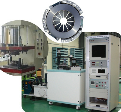
We are enlisted as one amidst the predominant Clutch Testing Machine manufacturers & Exporters from Kores. The Clutch Testing Machines, offered by us, have earned us loads of appreciation in the market due to the unmatched quality and unsurpassable performance.
Uses :
Automatic Testing of Electro Magnetic Clutches of Cars
Applications :
Testing of Electro - Magnetic Clutches and Brakes for their performance
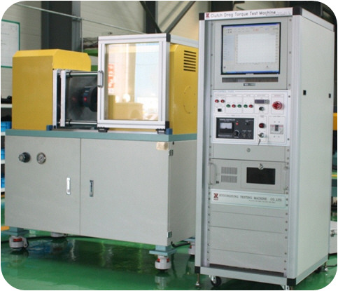
Clutch Drag Torque Test experimental rig was setup to test various groove patterns and verify the effects of clearance, rotation speed and groove depth.
utch Dynamometer is a computer operated servo controlled single end inertia type clutch dynamometer for the development and quality control of passenger car and truck clutch facings and assemblies. This machine contains the sophisticated controls necessary to apply the clutch properly. The control system is a multi-tasking real time enhanced computer system which utilizes our customized circuitry and software.
is checked visually so we can assure the veracity of simulating only a sector of the actual plate for computational efficiency. Thermocouples monitor oil temperatures as it enters the plates and when it is ejected out from the outer radius and a heater warms the oil if needed. The temperature rise resulting from viscous
The flow periodicity that could be affected by gravity
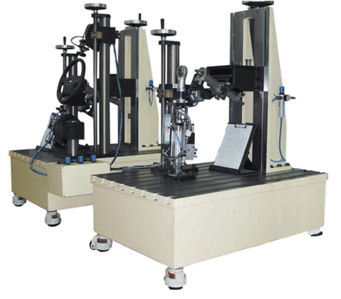
dissipation between the plates is small, at most 2C, and hence viscosity can be assumed to be constant. A 15 hp inverter-type motor 400–3450 rpm drives the rotating clutch plate. Centrifugal pump supplies oil throughout the system and the pump work and friction work between the plates increases the system temperature accordingly. The oil flow rate is precisely controlled by a displacement syringe pump that compresses two 50 ml syringes at a prescribed speed. When the inlet and outlet oil temperatures reach steady state, a valve attached to the centrifugal pump is closed to stop oil supply and the accurately metered, constant displacement syringe pump starts for the torque and optical measurements. A beam type single point load cell measures the drag torque of the stationary plate. Torque cell makes it possible to calculate the drag torque by multiplying the force measurement of the load cell by the moment length. A high-speed imager captures digital images through the transparent rotating plate at a rate of 4500 fps. A 500 W electrical heater installed in the oil sump allows experiments with elevated oil temperature. Transparent quartz rotating disk plate allows visualization of the flow pattern. The stationary plate is made of aluminum disk. To minimize the influence of the inner circular region, the stationary plate has a 4 mm depth very large compared to the clearances between the two plates that are 100 and 200 m step “d.” Five different stationary plates investigate the groove effect on drag torque. Four plates are made by two different numbers of grooves 40 and 80 and 2 groove depths 200 and 400 m combinations and a no groove plate flat disk is tested for generic experiment. Radial velocity versus axial coordinate. Radial velocity normalized with 2Rmh2 / and axial coordinates by h. Fig. 5 Axial velocity versus axial coordinate. These are normalized by 2h3 / and h, respectively. The circulation pump helps to maintain a steady oil temperature throughout. The syringe pump is used whenever a fixed flow rate of oil is to be prescribed. Steering Sub System Test This machine offers efficient and flexible test solution to perform dynamic tests on complete steering sub-system. By simulating its real environment, the test system eval!uates accurately the steering behavior in any configuration. By simulating loads applied on steering wheel and steering rack, This test machine can performed relevant dynamic tests :
For characterization of steering column, two optional modules are available to perform measurement of twist rigidity, friction torque and homokinetic defects.
• Columns and steering assembly positioned in real
configurations • High dynamic actuator to eval!uate steering behaviour • Power for steering assistance (electric or hydraulic) with CAN communication • User-friendly software with customizable interface • Steering column characterization with optional modules • Simulation of climatic conditions available, including mud sputtering • Power Constant regulation • Adjustable Voltage 0 to 18 V • Current output 150 A • Voltage or intensity Control by outside input Intensity measurement • Type Shunt measurement • Range 200 A • Accuracy 0.5% HYDRAULIC POWER SUPPLY FOR STEERING ASSISTANCE We can provide hydraulic power for steering assistance. Hydraulic circuit should be similar to vehicle circuit volume, about 1 liter. Flow, pressure and temperature measurements are integrated in the circuit. When real pump of hydraulic power assistance is connected, an asynchronous motor providing variable speed drives it. The pump is fixed on the motor by an interface. Several different interfaces can be provided. • Speed 0 to 1500 rpm • Power 7.5 kW • Torque 49 Nm simulate sensors or required information for ECU. The communication flow is created through CAN protocol. DBC files can be imported. Voltage measurement • Full Scale 20 V • Accuracy 0.1% FS For characterization of steering column, two optional modules are available to perform measurement of twist rigidity, friction torque and homokinetic defects. Sub-unit providing torque and measuring angle at the column’s end When the system is used without steering rack, this module provides torque on the column’s end through an electrical Brushless servo-motor: • Max. torque in rotation 10.6 Nm • Max. angular velocity 2000 °/s • Inertia 0.023 kg.m² • Feedback accuracy 0.1 Nm (in torque, in static) Low friction sub-unit This module is used for tests without steering rack which require low residual friction. It can be oriented in order to realize angular measures. Its rotation can be locked. • Setting in RY ± 45° • Setting in RZ ± 360° • Only 0.03 Nm residual friction torque in pinion shaft bearing Control System Motion CONTROLLERThe Motion controller is used to control the complete test system. It provides closed loop control for each axis, conditioning for sensor signals and integrates data acquisition module. Many types of sensors can be plugged, such as torquemeter, load cell, LVDT, flowmeter, pressure and temperature sensors, etc… For steering assistance system, full communication under CAN protocol is available. A remote control with programmable display is available for remote operation and monitoring. MOTION CONTROL SOFTWARE Motion control software which provides powerful control functions in a user-friendly environment. The Motion control software provides an easy-to-use “drag and drop” environment for building standard and non-standard sequences. In this environment, it is possible to link basic processes, including function generation (sinus, square, triangle, pause, imported file, etc…), data acquisition, events, and triggers, to quickly and easily build complex tests. Moreover, specific function provides the possibility to create customized control screens for test monitoring with graphical representation of any channel. Test report and standard data export are available too |
one electric motor simulating driver’s action on steering wheel and
two hydraulic cylinders applying load or displacement on steering rack. Each actuator can be closed loop controlled in displacement, speed or force. Hydraulic power pack is also available.
Power assistance modules can be added either for hydraulic or electric assistance systems.
Corresponding information are simulated through CAN communication to control vehicle electronic
commands.
Optional modules are also available to characterize steering column :
. A sub-unit to provide torque and measure angle at the steering column end
A sub-unit with low friction bearing & calibration arm
STEERING WHEEL ACTUATOR
It simulates the driver of the vehicle by providing active and reactive torque. It allows adjustments in every direction to meet vehicle configuration.
• Max. torque at low speed 56 Nm
• Min. angular velocity 0.1 °/s
• Max. angular velocity 2000 °/s
• Closed loop control in speed, torque or position
The torque meter is calibrated for two different ranges:
• Up to 50 Nm accuracy of 0.1 Nm
• Up to 5 Nm accuracy of 0.05 Nm
LOADING ACTUATOR ON STEERING RACK
Loads on the steering rack are provided by two hydrostatic bearing cylinders. Each actuator can
be adjusted in Z axis to match with real configuration.
• Max. load 9 kN
• Stroke 200 mm (LVDT position sensor)
• Max. speed 0.5 m/s (0.3 m/s dynamic)
Closed loop control in position / load
• Precision ± 0,1% from 0 to 25 Hz
• Frequency Max. 25 Hz
ELECTRIC POWER SUPPLY FOR STEERING ASSISTANCE
Electric power supply provides stable energy to the EPS & HPS in this electric cabinet. This station is mobile and can be used either on characterization or durability zone.
Voltage and current are controlled by test cycle. This
station is also connected to the BMC system
in order to communicate with CAN bus. Two input signals are simulated to control electronic vehicle command: vehicle speed and engine speed.