 |
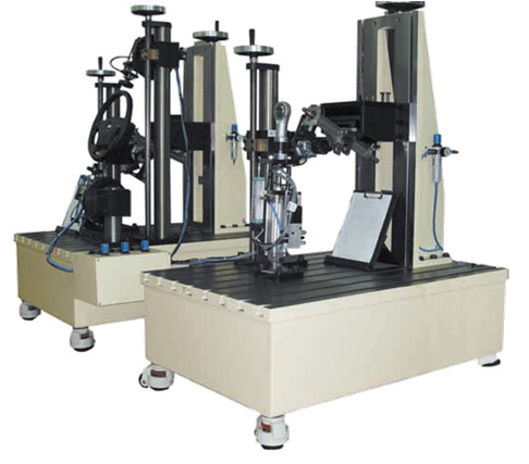
Steering Sub System Test
This machine offers efficient and flexible test solution to perform dynamic tests on complete steering sub-system. By simulating its real environment, the test system eval!uates accurately the steering behavior in any configuration.By simulating loads applied on steering wheel and steering rack, This test machine can performed relevant dynamic tests :
|
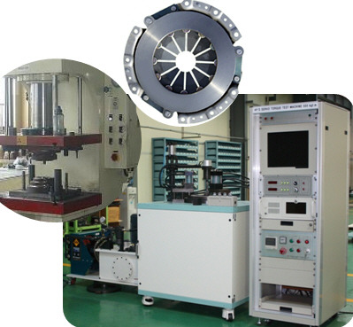 |
We are enlisted as one amidst the predominant Clutch Testing Machine manufacturers & Exporters from Kores. The Clutch Testing Machines, offered by us, have earned us loads of appreciation in the market due to the unmatched quality and unsurpassable performance.
Uses :
Automatic Testing of Electro Magnetic Clutches of Cars
Applications :
Testing of Electro - Magnetic Clutches and Brakes for their performance
|
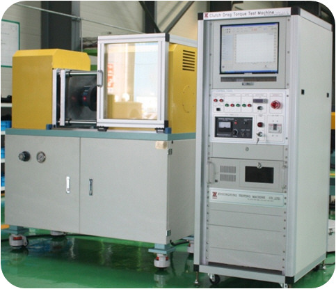
Clutch Drag Torque Test
This experimental rig was setup to test various groove patterns and verify the effects of clearance, rotation speed and groove depth.
This Clutch Dynamometer is a computer operated servo controlled single end inertia type clutch dynamometer for the development and quality control of passenger car and truck clutch facings and assemblies. This machine contains the sophisticated controls necessary to apply the clutch properly. The control system is a multi-tasking real time enhanced computer system which utilizes our customized circuitry and software.
· Digital Servo Valve for stop time control within 0.001 seconds, pressure ramp engagements, pressure/force controlled engagements
· Continuous slip speed ramp capabilities for friction mapping of torque converters, torque transfer couplings, limited slip differentials and fluid eval!uations
· Switching from dynamic to static to continuous slip mode or any combination without operator interaction
· Programmable test fluid flow and sump temperature control.·
· Automatic test fluid viscosity/flowadjustment
· Automatic test report generatior
The flow periodicity that could be affected by gravity is checked visually so we can assure the veracity of simulating only a sector of the actual plate for computational efficiency. Thermocouples monitor oil temperatures as it enters the plates and when it is ejected out from the outer radius and a heater warms the oil if needed. The temperature rise resulting from viscousdissipation between the plates is small, at most 2C, and
hence viscosity can be assumed to be constant.
A 15 hp inverter-type motor 400–3450 rpm drives the
rotating clutch plate. Centrifugal pump supplies oil throughout the system and the pump work and friction work between the plates increases the system temperature accordingly. The oil flow rate is precisely controlled by a displacement syringe pump that compresses two 50 ml syringes at a prescribed speed. When the inlet and outlet oil temperatures reach steady state, a valve attached to the centrifugal pump is closed to stop oil supply and the accurately metered, constant displacement syringe pump starts for the torque and optical measurements. A beam type single point load
cell measures the drag torque of the stationary plate.
Torque cell makes it possible to calculate the drag torque by multiplying the force measurement of the load cell by the moment length. A high-speed imager captures digital images through the transparent rotating plate at a rate of 4500 fps. A 500 W electrical heater installed in the oil sump allows experiments with elevated oil temperature.
Transparent quartz rotating disk plate allows visualization
of the flow pattern. The stationary plate is made of aluminum disk. To minimize the influence of the inner circular region, the stationary plate has a 4 mm depth very large compared to the clearances between the two plates that are 100 and 200 m step “d.” Five different stationary plates investigate the groove effect on drag torque. Four plates are made by two different
numbers of grooves 40 and 80 and 2 groove depths 200 and 400 m combinations and a no groove plate flat disk is tested for generic experiment.
Radial velocity versus axial coordinate. Radial velocity
normalized with 2Rmh2 / and axial coordinates by h.
Fig. 5 Axial velocity versus axial coordinate. These are normalized by 2h3 / and h, respectively.
The circulation pump helps to maintain a steady oil temperature throughout. The syringe pump is used whenever a fixed flow rate of oil is to be prescribed.