Earthquake Simulation for Base Isolation


Base isolation is an important strategy for protecting structures from earthquake excitations. Base isolation attempts to isolate a structure from the external ground excitations. This has prompted great interest in the viability of base isolation for seismic protection of Civil structure. It is meant to protection enable building or non-building structure to survive in earthquake impact through a proper initial design or subsequent modifications

This simulator considers multiple cases: 
The user can vary the properties of the structure, the isolation system and the earthquake motion, allowing for insight into the influence of various parameters on the responses of the system. Animation of the user designed systems facilitates visualization of parameter effects. The base isolation simulation is intended to be used to increase understanding and provide a conceptual "feel" for various parameter changes on the performance of base isolated systems.

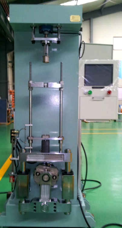
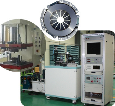
This Simulator offers how to operate and use the Shaking Table for Base Isolation Simulation, a picture of which is shown below.


Research & Development Solution:
Shake Table – With the continual introduction of international building codes and regulations the importance of seismic resistant design is becoming increasingly important for most building structures. The shake table presents more advanced analysis with the introduction of dynamics of particular interest and value for structural dynamics research efforts and earthquake loss reduction.
Description:
A high-powered system for advanced research and curriculum the Table features:
  • A maximum acceleration of 1.5g at full load.
  • Maximum load of 120kg
  • Maximum Velocity of 600 mm/sec
  • High precision low friction linear bearings
  • Linear motor no hydraulics or cams:
    allows for greater precision of position and table displacement
  • Optional structure model:4 stories of nuclear plant dom constructions.
  • Base Isolation Bearing
  • Cost effective
Application:
Custom built for a research application the Table is generally available for a fraction of the cost of other high-powered systems in a similar class.

MOTOR ASSEMBLY


Automatic Motor Assembly Line 

Automatic loading
Automatic coil winding
Automatic vision inspection
Automatic unloading

Damping Terst

 SHOCK ABSORBER TESTING
 We find the speed characteristic and the feed motion characteristic of damping by testing. In the following text are shown various methods of testing.
Testing removed shock absorbers
Testing equipment is a special dynamometer (shown in Figure). The damping force is measured for variable speed of motion and strokes in this case. The advantage of testing on removed shock absorbers is that the characteristics are not affected by the entire suspension system (stiffness of tyres, arms, joints and springs).


Environment - Shock Absorbers Test 
Ride comfort and safety are amongst the most important criteria when it comes to selecting a car. High speeds in particular make highest demands on modern vibration damper systems. Damper systems, McPherson struts and shock absorber systems used in modern axle designs, often electronically controlled, are exposed to extreme loads and they have to be capable of adapting their damping properties to varying driving conditions within milliseconds. Depending on the design criteria and vehicle type concerned, shock absorbers may have entirely different characteristics.

Multi - Shock Absorbers Test 
One, Two, Four or Six -
Test as Many Shock Absorbers as You Wish Shock absorber test system
d IST has been developing servohydraulic shock
absorber testing systems for around 30 years.
MSP test machines are based on this wealth of experience. They are conceived to analyse and assess accurately and reliably the material properties and characteristic parameters of single-tube and twin-tube shock absorbers, driver's cab dampers, seat and steering dampers and metallic impact absorbers.
User-friendly application software running
under Windows® enables input of all relevant
parameters, customizing of analysis
procedures and storage of test procedures and measurement data. IST's MSP test system is
therefore the ideal tool for reliable, fast and
realistic tuning of vehicle chassis designs and
development of shock absorber systems.

Automotive Test


We are enlisted as one amidst the predominant Clutch Testing Machine manufacturers & Exporters from Kores. The Clutch Testing Machines, offered by us, have earned us loads of appreciation in the market due to the unmatched quality and unsurpassable performance.
Uses : 
Automatic Testing of Electro Magnetic Clutches of Cars

Applications :
Testing of Electro - Magnetic Clutches and Brakes for their performance

Clutch Drag Torque Test experimental rig was setup to test various groove patterns and verify the effects of clearance, rotation speed and groove depth.

utch Dynamometer is a computer operated servo controlled single end inertia type clutch dynamometer for the development and quality control of passenger car and truck clutch facings and assemblies. This machine contains the sophisticated controls necessary to apply the clutch properly. The control system is a multi-tasking real time enhanced computer system which utilizes our customized circuitry and software.  
  • Digital Servo Valve for stop time control within 0.001 seconds, pressure ramp engagements, pressure/force controlled engagements
  • Continuous slip speed ramp capabilities for friction mapping of torque converters, torque transfer couplings, limited slip differentials and fluid eval!uation
  • Switching from dynamic to static to continuous slip mode or any combination without operator interactionn
  • Programmable test fluid flow and sump temperature control
  • Automatic test fluid viscosity/flow adjustment
  • Automatic test report generator report generation
The flow periodicity that could be affected by gravity
is checked visually so we can assure the veracity of simulating only a sector of the actual plate for computational efficiency. Thermocouples monitor oil temperatures as it enters the plates and when it is ejected out from the outer radius and a heater warms the oil if needed. The temperature rise resulting from viscous

dissipation between the plates is small, at most 2C, and
hence viscosity can be assumed to be constant.
 A 15 hp inverter-type motor 400–3450 rpm drives the
rotating clutch plate. Centrifugal pump supplies oil throughout the system and the pump work and friction work between the plates increases the system temperature accordingly. The oil flow rate is precisely controlled by a displacement syringe pump that compresses two 50 ml syringes at a prescribed speed. When the inlet and outlet oil temperatures reach steady state, a valve attached to the centrifugal pump is closed to stop oil supply and the accurately metered, constant displacement syringe pump starts for the torque and optical measurements. A beam type single point load
cell measures the drag torque of the stationary plate.
Torque cell makes it possible to calculate the drag torque by multiplying the force measurement of the load cell by the moment length. A high-speed imager captures digital images through the transparent rotating plate at a rate of 4500 fps. A 500 W electrical heater installed in the oil sump allows experiments with elevated oil temperature.
Transparent quartz rotating disk plate allows visualization
of the flow pattern. The stationary plate is made of aluminum disk. To minimize the influence of the inner circular region, the stationary plate has a 4 mm depth very large compared to the clearances between the two plates that are 100 and 200 m step “d.” Five different stationary plates investigate the groove effect on drag torque. Four plates are made by two different
numbers of grooves 40 and 80 and 2 groove depths 200 and 400 m combinations and a no groove plate flat disk is tested for generic experiment.
Radial velocity versus axial coordinate. Radial velocity
normalized with 2Rmh2 / and axial coordinates by h.
Fig. 5 Axial velocity versus axial coordinate. These are normalized by 2h3 / and h, respectively.
 The circulation pump helps to maintain a steady oil temperature throughout. The syringe pump is used whenever a fixed flow rate of oil is to be prescribed.


Steering  Sub System Test       

This machine offers efficient and flexible test solution to perform dynamic tests on complete steering sub-system. By simulating its real environment, the test system eval!uates accurately the steering behavior in any configuration.
By simulating loads applied on steering wheel and steering rack, This test machine can performed relevant dynamic tests :

  • Violent wheel swerve :. acceleration up to 15 000 °/s with 6 000 N resistance force on rack
  •  Wheel release after wheel turn :
    steering column behavior after wheel releasing, under real load on the rack
  • Frequency characterization (direct or reverse) :
    system response measurement under vibration (force/displacement)
  • Derating : power electronics failure analysis

For characterization of steering column, two optional modules are available to perform measurement of twist rigidity, friction torque and homokinetic defects.

• Columns and steering assembly positioned in real
configurations
• High dynamic actuator to eval!uate steering behaviour
• Power for steering assistance (electric or hydraulic) with CAN communication
• User-friendly software with customizable interface
• Steering column characterization with optional modules
• Simulation of climatic conditions available, including
mud sputtering

• Power Constant regulation
• Adjustable Voltage 0 to 18 V
• Current output 150 A
• Voltage or intensity Control by outside input
  Intensity measurement
• Type Shunt measurement
• Range 200 A
• Accuracy 0.5%

HYDRAULIC POWER SUPPLY FOR STEERING ASSISTANCE
We can provide hydraulic power for steering assistance. Hydraulic circuit should be similar to vehicle circuit volume, about 1 liter. Flow, pressure and temperature measurements are integrated in the circuit.
When real pump of hydraulic power assistance is connected, an asynchronous motor providing variable speed drives it. The pump is fixed on the motor by an interface. Several different interfaces can be provided.
• Speed 0 to 1500 rpm
• Power 7.5 kW
• Torque 49 Nm


In any case, a communication module of the control system generates actual electric signals to
simulate sensors or required information for ECU. The communication flow is created through
CAN protocol. DBC files can be imported.
Voltage measurement

• Full Scale 20 V
• Accuracy 0.1% FS


OPTIONAL MODULES, STEERING COLUMNS CHARACTERIZATION
For characterization of steering column, two optional modules are available to perform measurement of twist rigidity, friction torque and homokinetic defects.

Sub-unit providing torque and measuring angle at the column’s end
When the system is used without steering rack, this module provides torque on the column’s end
through an electrical Brushless servo-motor:
• Max. torque in rotation 10.6 Nm
• Max. angular velocity 2000 °/s
• Inertia 0.023 kg.m²
• Feedback accuracy 0.1 Nm (in torque, in static)

Low friction sub-unit
This module is used for tests without steering rack which require low residual friction.
It can be oriented in order to realize angular measures. Its rotation can be locked.
• Setting in RY ± 45°
• Setting in RZ ± 360°
• Only 0.03 Nm residual friction torque in pinion shaft   bearing

Control System
Motion CONTROLLERThe Motion controller is used to control the complete test
system. It provides closed loop control for each axis, conditioning for sensor signals and integrates data acquisition module. Many types of sensors can
be plugged, such as torquemeter, load cell, LVDT, flowmeter, pressure and temperature sensors, etc… For steering assistance system, full communication under CAN protocol is available.
A remote control with programmable display is available
for remote operation and monitoring.
MOTION CONTROL SOFTWARE
Motion control software which provides powerful control
functions in a user-friendly environment.
The Motion control software provides an easy-to-use “drag and drop” environment for building standard
and non-standard sequences. In this environment, it is possible to link basic processes, including function generation (sinus, square, triangle, pause, imported file, etc…), data acquisition, events, and triggers, to quickly and easily build complex tests.
Moreover, specific function provides the possibility to create customized control screens for test monitoring with graphical representation of any channel. Test report and standard data export are available too
  This test rig integrates three main actuators:
one electric motor simulating driver’s action on steering wheel and
two hydraulic cylinders applying load or displacement on steering rack. Each actuator can be closed loop controlled in displacement, speed or force. Hydraulic power pack is also available.
Power assistance modules can be added either for hydraulic or electric assistance systems.
Corresponding information are simulated through CAN communication to control vehicle electronic
commands.

Optional modules are also available to characterize steering column :

. A sub-unit to provide torque and measure angle at the steering column end
 A sub-unit with low friction bearing & calibration arm


STEERING WHEEL ACTUATOR
It simulates the driver of the vehicle by providing active and reactive torque. It allows adjustments in every direction to meet vehicle configuration.


• Max. torque at low speed 56 Nm
• Min. angular velocity 0.1 °/s
• Max. angular velocity 2000 °/s
• Closed loop control in speed, torque or position
  The torque meter is calibrated for  two  different  ranges:
• Up to 50 Nm accuracy of 0.1 Nm
• Up to 5 Nm accuracy of 0.05 Nm

LOADING ACTUATOR ON STEERING RACK
Loads on the steering rack are provided by two hydrostatic bearing cylinders. Each actuator can
be adjusted in Z axis to match with real configuration.


• Max. load 9 kN
• Stroke 200 mm (LVDT position sensor)
• Max. speed 0.5 m/s (0.3 m/s dynamic)
  Closed loop control in position / load
• Precision ± 0,1% from 0 to 25 Hz
• Frequency Max. 25 Hz


ELECTRIC POWER SUPPLY FOR STEERING ASSISTANCE
Electric power supply provides stable energy to the EPS & HPS in this electric cabinet. This station is mobile and can be used either on characterization or durability zone.
Voltage and current are controlled by test cycle. This

station is also connected to the BMC system
in order to communicate with CAN bus. Two input signals are simulated to control electronic vehicle command: vehicle speed and engine speed.
.


About US

Start Motor Test Equipment


START MOTOR TEST EQUIPMENT


본 사양서는 「환경친화적 산업구조로의 전환촉진에 관한 법률 시행령」제12조제3항에 따른「자동차용 재제조 시동전동기 품질인증기준」에 따라 자동차용 재제조(Remanufacturing) 시동전동기(이하 “시동전동기”라 한다) 품질인증기준에 따라 이를 시험하기 위한 시험장비를 설계, 제작, 설치 하는 내용 및 필요한 정보를 제공함을 기술하는 것을 그 목적으로 하며, 이러한 기능을 충분히 수행 할 수 있게 다음과 같은 조건을 충족 시킬 수 있게 설계한다.

2     1. 장비의 개요  


본 시험장비는 본 시험기는 자동차용 STARTMOTOR의 내구성을 시험하는 장비로서 환경친화적 산업구조로의 전환촉진에 관한 법률 시행령」제12조제3항에 따른「자동차용 재제조 교류발전기 품질인증기준」에 따라 자동차용 재제조(Remanufacturing) 교류발전기를 의 시험기준에 맞게 장비를 설계, 제작 한다.  본 장비는 STARTMOTOR 의 종합성능 시험기로서 컴퓨터를 이용하여 회전수, 부하, 소음 및 온도 환경 변화에 대한 STARTMOTOR의 응답성 및 내구성을 측정하여 각 시험 조건에 대한 STARTMOTOR의 특성을 모니터링하고 데이타를 출력하는 기능을 가진 장비이다.
본 장비는 STARTMOTOR의 품질. 성능시험을 할 수 있으며 측정 Data Graphic 처리하여 보다 효율적으로 각 성능들을 분석 할 수 있도록 설계하였다. 시험은 컴퓨터에 의해 수동과 자동으로 운용되며, 실시간으로 그래픽 형태로 모티터 화면에 표시되고, 데이터를 저장하고, 시험 결과를 성적서 형태롤 출력한다,

시험장비의 시험항목.
A.    출력 성능 시험
   
무부하시험
   
부하시험
   
구속시험
B.     절연저항 시험
C.    소음 시험
D.    전압강하시험
E.     스돕핑시험
G.    솔레노이드 홀드인 전압 시험
H.    진동시험
I.      착화내구 성능시험


3      2. 장비의 구성  


2.1 SYSTEM BLOCK DIAGRAM


Motor Power Supply
소음챔버                                    
Power Absorber
microphone


Power Absorber  Controller
Torque /RPM
시동모터            
V                                                                                      
V                                                                  Volt/Am,pare/ohm
2.2  장비의 구성
2.2.1 장비의 규격
<></><></><></><></><></><></><></><></><></><></><></><></><></><></><></><></><></><></><></><></><></><></>
최대  ABSORBER 회전속도
4,000 RPM
최대  ABSORBER 토크
28Nm
최대  ABSORBER  Power
4,000W
Power Supply
DC 15V, 1000A
절연저항
>1Mohm(DC500V)
소음챔버
<10dB
진동
25G, 300Hz
마이크로폰
120dB, FFT
회전수 검출
비접촉 검출
환경챕버
Room~150


                                 모터 fixture
Power Supply
IN PUT VOLTAGE AC 220V 1Ø,  60Hz
OUT PUT VOLTAGE DC 0~15V
OUT PUT CURRENT DC 0~1000.0A

Control and Data Acquisition
The high-speed control option includes serial interface:
     Dual digital signal processors (DSPs)
     All aspects of the drive connected to the torque meter and power analyzer.
     Control capabilities for load, drive motor, and product under test
     Internal torque feedback estimator (99.5% accurate)
     The data acquisition system is set up to acquire 1~10,000 readings per second.
     The measured data can be stored directly to an excel-file.
     DAQ Instrumentation records shaft power.
     Speed, torque and power are displayed.
     Simply click on a virtual connectors in configuration screen
     Windows XP OS Based Software.
     Multiple test sequences.


Software


계측기
절연저항측정기(TOS-7200)
출력부:전압 [AC -25~-1000V, 분해능1V], 최대 정격 전류 [1mA], 전압 변동률 [1%]
전압계:측정범위[0~1200V],분해능 [1V], 정확도 ±(1% of reading+1V)
저항계:측정범위 [0.01MΩ~ 5000MΩ (100mA 초과 1mA 까지의 범위 내), 정확도 [1~1mA에서 ±(2% of reading)]
시험 결과 판정 동작:패널 표시, 버저안전관련 시험기, I/O신호 출력
● RS-232C 인터페이스
전원:AC100~240V
부속 테스트리드:TL08-TOS

6 1/2 Digit Digital Multimeter
Stability, Speed and Accuracy The 6 1/2 digit M3500A DMM is designed with 71/2 digit techniques to provide user a stable, faster and accurate measurement. The following figure is the stability performance comparison between the typical 61/2 digit DMM and the M3500A.
There are 11measurements and 8 math functions : DCI, DCV, ACI, ACV, 2WΩ, 4WΩ, Frequency, Period, Diode Test, Continuity, Temperature, Limits, Ratio, MX+B, %, dB, dBm, Min/Max, and Null. In addition, Trigger and Memory functions are also involved.
All functions above facilitate your measurement applications better.

Digital Sound Level Meters
Features:
0.1dB resolution
Fast/slow response
Max Hold with reset button
Model 407736 meets ANSI and IEC 651 Type II standards
Large 0.5" 3-1/2 digit LCD display
Built-in calibration check (94dB)
Tripod mount and analog DC/AC conditioned outputs of 10mV/dB
Utilizes 0.49"(12.3mm) condenser microphone
Dimensions: 9.5 x 2.7 x 1" (241 x 69 x 25mm) Weight: 7.6 oz (215g)
Complete with hard vinyl case and 9V battery